
Assembly instructions for modular threading die Type MSE

The mounting principle applies to all thread sizes and cutting speeds.
- First, install the abutment into the puncture of the carrier body, align the holes and expansion slots.
- After the attachment has been installed in the cutting edge, the screws and clamping wedges come into the grooves. Here the order is arbitrary, the wedges should protrude 2 to 3 mm.

After the support body and clamping wedges have been installed, the cutting plates can be used.
In this case, the numbering of the cutting plates must correspond to that of the plate seat. The first digit stands for plate seating, the second for the number of cutting edges in the set.
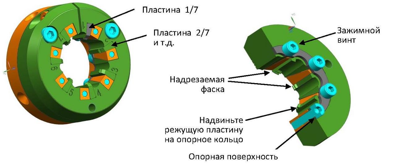
For example, start with the number 1/7 in the plattensitz 1. Then number 2/7 in the plattensitz 2 u.s.w.
The bearing plan can be pressed onto the contact surface with slight pressure on the clamping screw.
The chamfering edge must always be outside!
Push the cutting plate into the seat with light pressure until it rests against the bearing ring.
Tighten the clamping screw with 1 Nm and install all cutting edges in this way. Then tighten all bolts with 2.5 Nm.
Now screw the completely mounted carrier body to the holder:
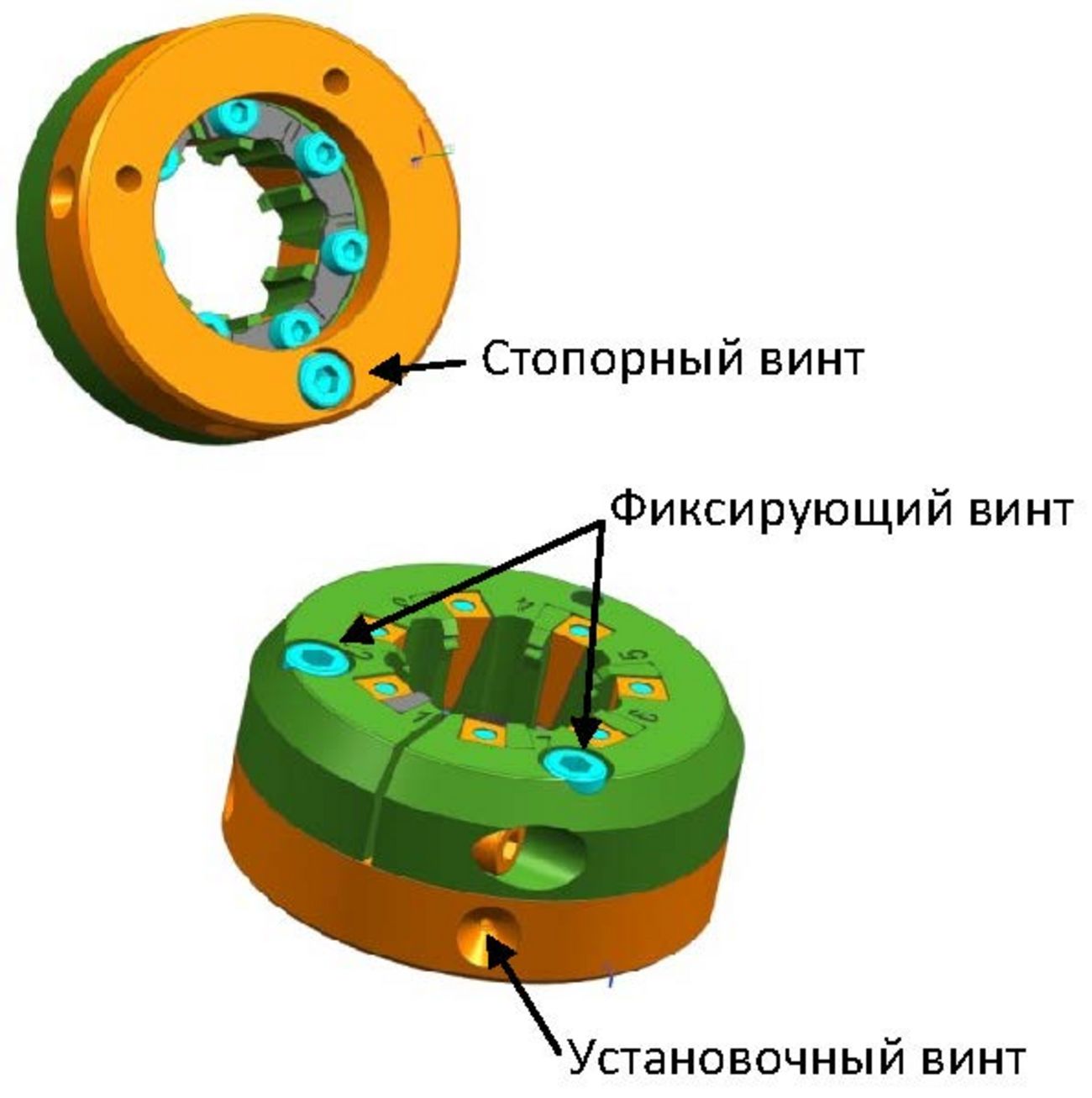
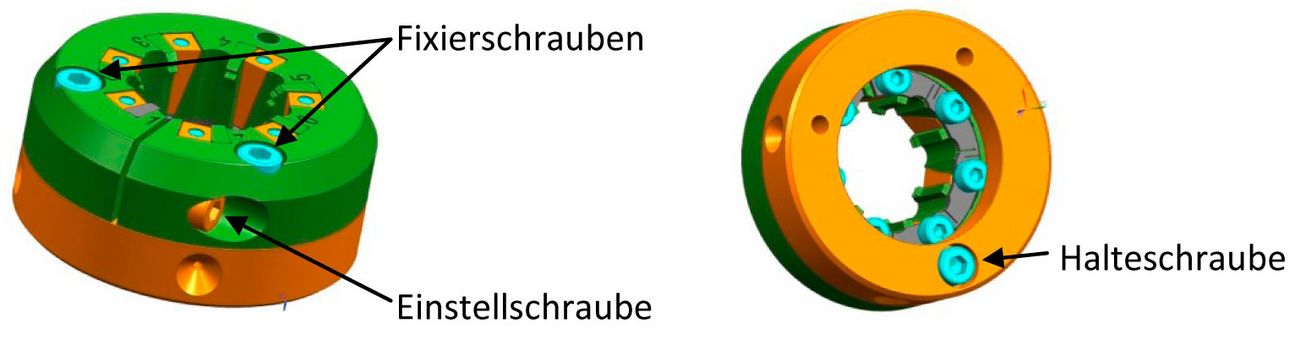
- Screw in the retaining screw (back)
- Align the support body and the holder
- Tighten the retaining screw to 4 Nm
- Insert the locking screws on the front (without a suit)
- Insert the adjusting screw and adjust the cutting edges with a dimensioned workpiece until it can be turned in and out without play
- Now tighten the fixing screws with 4 Nm
- If necessary, repeat the adjustment (open the fixing screws, adjust the adjustment screw until the workpiece is taught, then tighten the fixing screws again)
Disassembly:
- Unscrew the fixing screws and loosen the adjusting screw
- Unscrew the retaining screw and remove the holder
- Unscrew the clamping screws 2 to 3 turns
- On the respective screw head give a slight blow,
- In order to release the self-locking of the clamping wedge
- Now all elements can be dismantled
When new parts are installed, please clean all parts thoroughly!
